21. Widgets and Tools
21.1. Introduction to Widgets
This chapter describes the on-screen widgets, instruments, and panels, in the order they appear on the Widgets menu of the In-Flight Menu Bar. The transmitter panels on the Transmitter menu follow at the end. Every one of them has a key, given with its name below, and every one is on the menu bar, so you never have to remember the key.
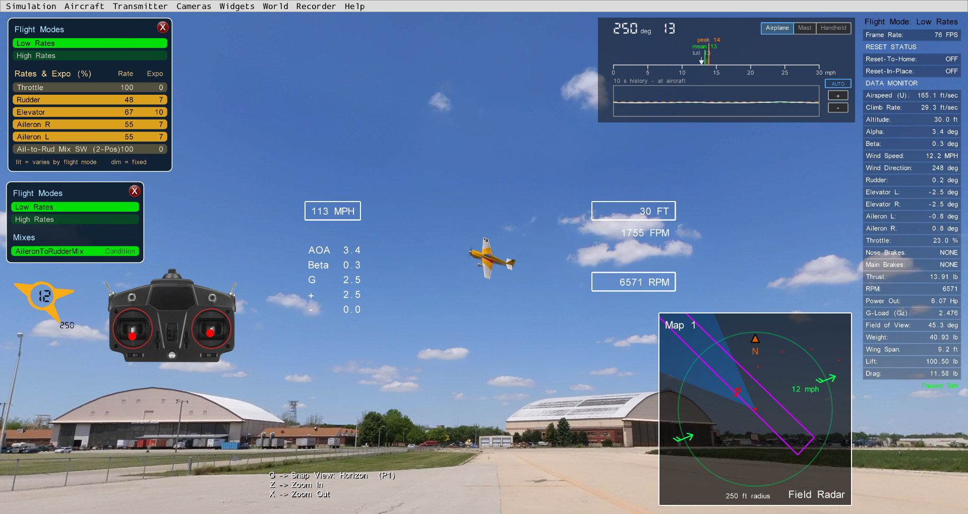
Some of the on-screen widgets and panels in SeligSIM.
A few things are true of all of them:
Every widget is draggable. Each one reopens where you left it, between flights and across restarts. Power Tools sets where each one starts, and Widgets | Reset All Widget Positions forgets what you moved.
Widgets whose edges are invisible (the Transmitter Display, Screencast Keys, Height & Distance, Wind Compass) outline themselves in cyan while you drag them.
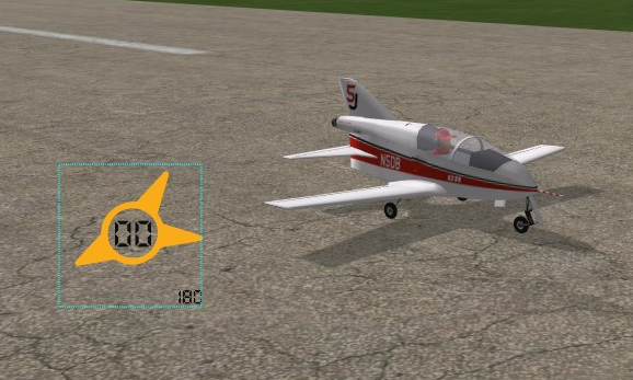
A borderless widget outlines itself while dragged (the Wind Compass here).
A one-line “Onscreen Widgets:” message at the start of each flight says whether the layout came from Power Tools, from the last flight, or from a playback.
Widgets | Close All clears the screen.
Widgets | Widget Sizes… resizes any of them in flight, with one slider per widget, the HUD, and the Data Monitor text. Instruments resize as you drag the sliders, panels and maps at the next flight, and the window says which is which. One Tx Panels slider sizes all the transmitter panels together.
Readouts follow the units you chose in Options | Physics, or flip them for the session with
Left Shift+U.
21.2. Airplane Specifications
Press Left Shift + KP / (the keypad slash), or pick it from
the Aircraft menu, to open the Airplane Specifications panel, the
airplane’s specification sheet as a panel that stays up. For airplanes that are scaled up or down, it
gives insightful information about the characteristics of the
airplane. For more details, see the chapter on the
Scaling Wizard.
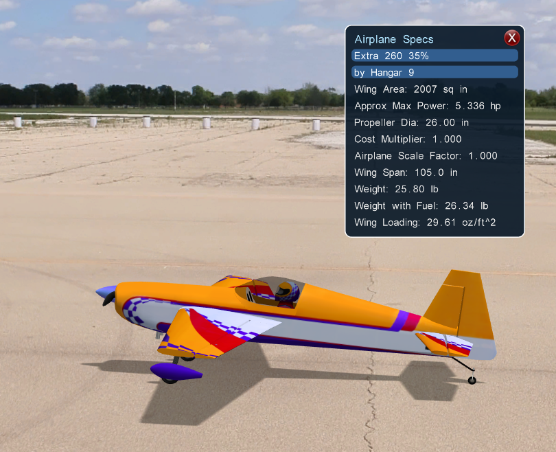
Airplane Specifications - Unscaled Extra 260.
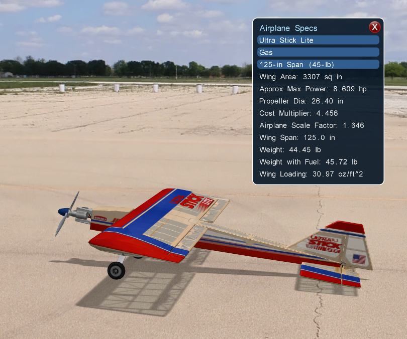
Airplane Specifications - Scaled up Ultra Stick with estimated cost 4.5 times the original scale.
21.3. Screencast Keys
Press Left Shift + / and every key you press appears on
screen with the action it ran. Leave it on for a flight and the sim
teaches you its own keyboard. It draws into screenshots and video, so
a recorded flight explains its own keystrokes.
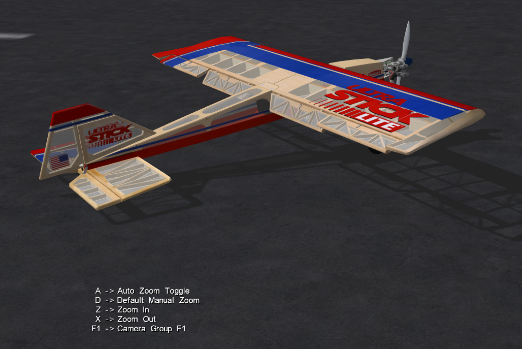
Screencast Keys Left Shift + / .
21.4. Field Map
The Field Map shows an overhead view of your aircraft relative to
the runway. Press M repeatedly to cycle through the maps and then
hide the map. Each press names the map that came up, e.g., “Map 1:
Field Radar”. The five maps read the same on the map, on the Widgets
menu, and in Power Tools, where you can also choose which of the five
the M key stops at.
Each map shows a top-down view of:
Your aircraft (red), and pilot 2’s aircraft in a two pilot session
Recordings, as ghosts
View direction indicator (“view fan” in blue), its width the field of view
Runway or natural site boundary (purple line)
Wind, and the windsock with a tail cone pointing downwind
Pilot standing positions and the launch line
Flight path ground track markers with a fading red tail
Race course pylons during pylon racing, and target locations in the bomb drop game (red circles)
Thermals, sized to their usable lift (World | Thermals on Field Maps)
The five maps:
Map 1: Field Radar is the default, a stable, pilot-centered radar scope with range rings that never “breathes” or slides away. When the airplane flies past the outer ring, an off-map arrow with the distance points at it. A North marker is on the ring.
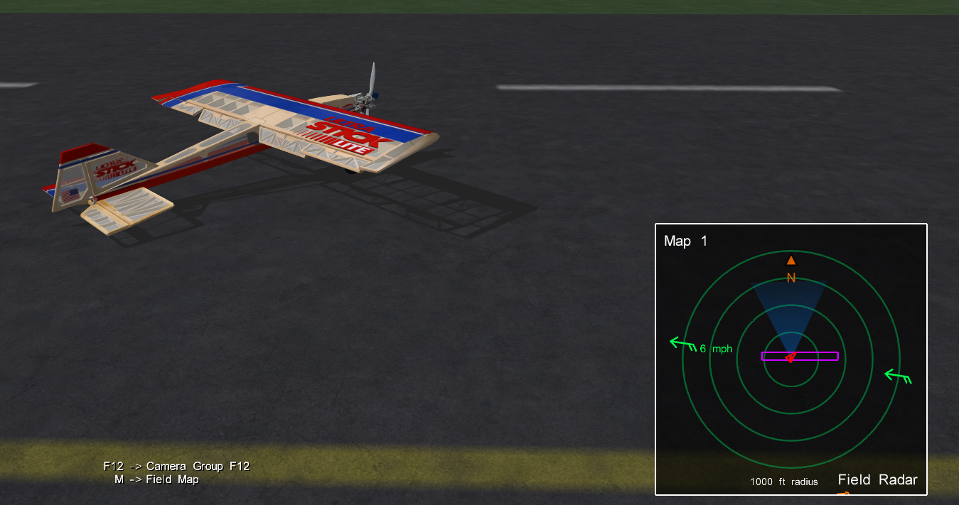
Map 1: Field Radar M .
Map 2: Runway-Aligned. Up is typically north, but depending on the field the map may be rotated such that “up” could instead be south, east, or west. The runway is fixed and you see your aircraft (red) fly around. The view fan is the direction that you are looking, whether you are standing fixed on the ground (
F1view) or flying along with the aircraft using an onboard camera (F8view).

Map 2: Runway-Aligned M .
Map 3: North-Up. Like the runway-aligned map, but north is always up.
Map 4: View-Aligned. The view direction is always pointed up on-screen (see below). The aircraft and runway move around the fixed view fan.

Map 4: View-Aligned M .
Map 5: Aircraft-Aligned (up on-screen is flight direction). The runway and view fan move around the fixed aircraft. This map is helpful when using a chase camera view (
F6, see Camera Views).

Map 5: Aircraft-Aligned M .
21.5. Orientation Map
Press Left Shift + M for the Orientation Map, a circular
map centered on your airplane, nose up, the way a drone radar works.
One glance answers “which way is it pointing, and which way is home?”
Press again for a north-up wall-map view, and again to hide it. It
shows thermals sized to usable lift, other aircraft, wind, sun, and
your view cone. Widgets | Orientation Map | Settings… opens a window for the disc’s frame, what it
shows, and its sizes, live while you fly.
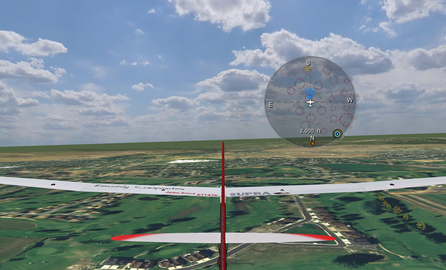
Orientation Map Left Shift + M , heading up.
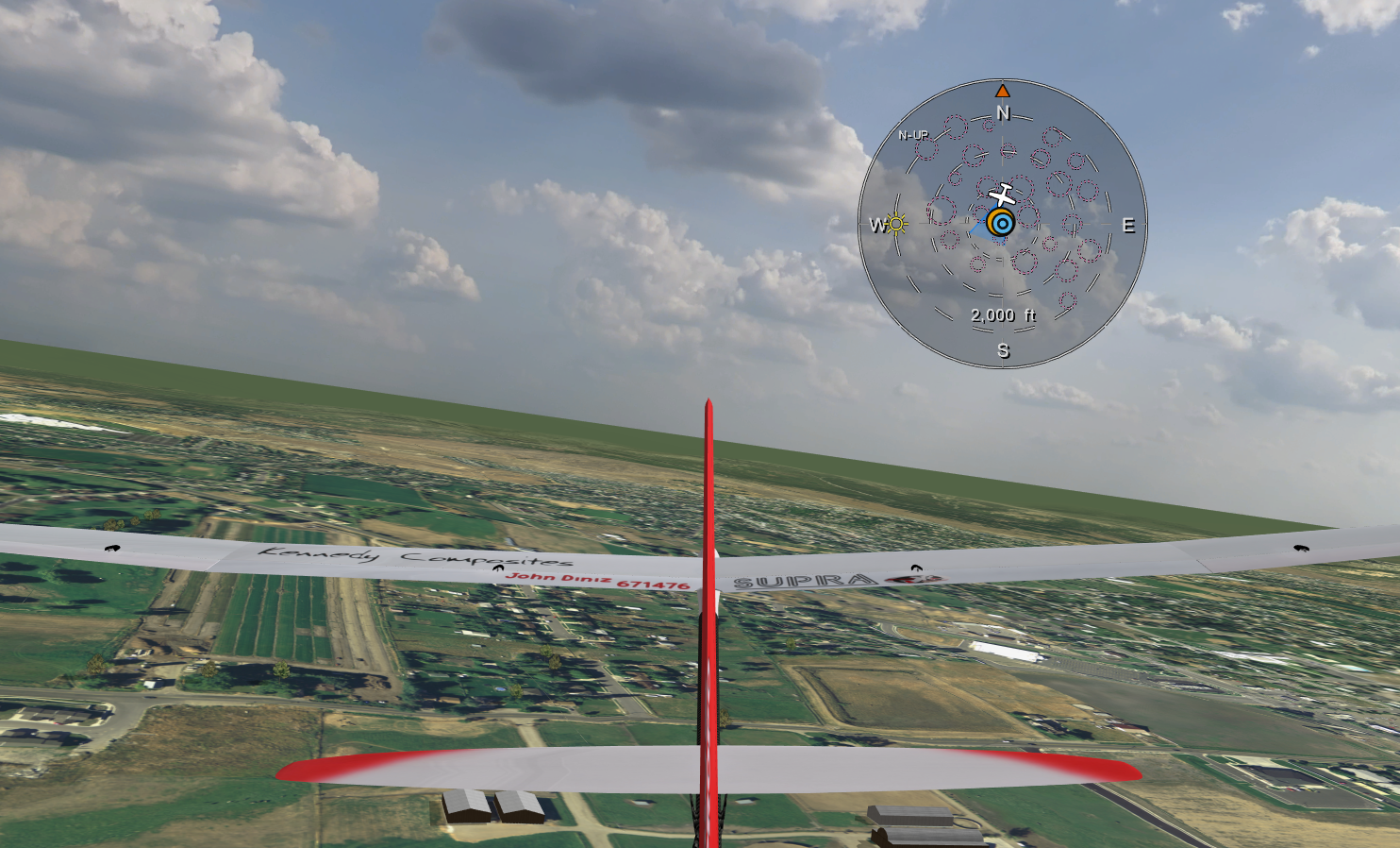
Orientation Map, north up.
21.6. HUD (Heads-Up Display)
Press H to show the HUD. Repeating H key presses will cycle
through 7 different HUD display styles. Three examples are shown below.
HUD messages age in place. An expired line goes blank and the lines
below stay put, so the stack never jumps while you are reading it.
The HUD’s return-to-home arrow shows only in views that follow the
airplane, where its direction makes sense. Both of its switches,
Home Arrow and Home Arrow Only in Following Views, are on
Widgets | HUD. The HUD choice is remembered
between flights.


Example HUD layouts H .
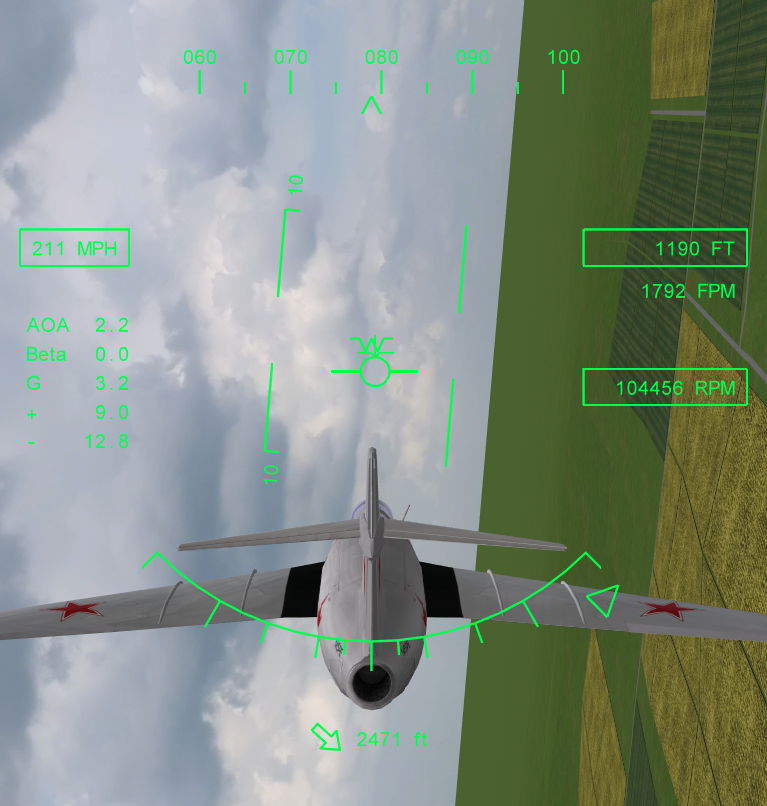
HUD with the return-to-home arrow, the green arrow centered at the
bottom. This is a following view, the F8 view from the tail of
the MiG-15.
SeligSIM Modding Tip
The HUD list and files defining the layout and color of each HUD are in the SeligSIM install folder ~/HUD.
21.7. Height & Distance
Press Left Shift + H for a drone-style corner readout. It
shows height above you with climb rate, and distance out with ground
speed.
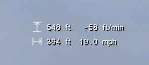
Height & Distance Left Shift + H .
21.8. Wind Compass and Magnetic Compass
Press W to turn on the Wind Compass. The arrow points to where
the wind is blowing from, simulating a perfect weathervane.
A basic Magnetic Compass can be displayed by pressing C . As the
view direction follows the aircraft, the compass will naturally change
its visual orientation, while always pointing north.

Magnetic Compass C and Wind Compass W .
21.9. Wind Meter
Press Left Shift + W for the Wind Meter, which shows the
wind at your airplane. It is an aviation-style direction, speed, and gust readout
in LED digits, with a speed scale carrying lull, average, and peak
markers. The orange band on the scale is the gustiness. Below it, a
strip chart shows the last seconds of wind.
The meter ranges itself, or you can pick a fixed scale with its + / - buttons. Gusts are smoothed with the 3-second aviation standard. And the wind can be sampled at the airplane, at a 10 m (33 ft) field mast, or at a handheld height you set. Every wind readout in the sim follows the same choice. These settings are on Widgets | Wind Meter.
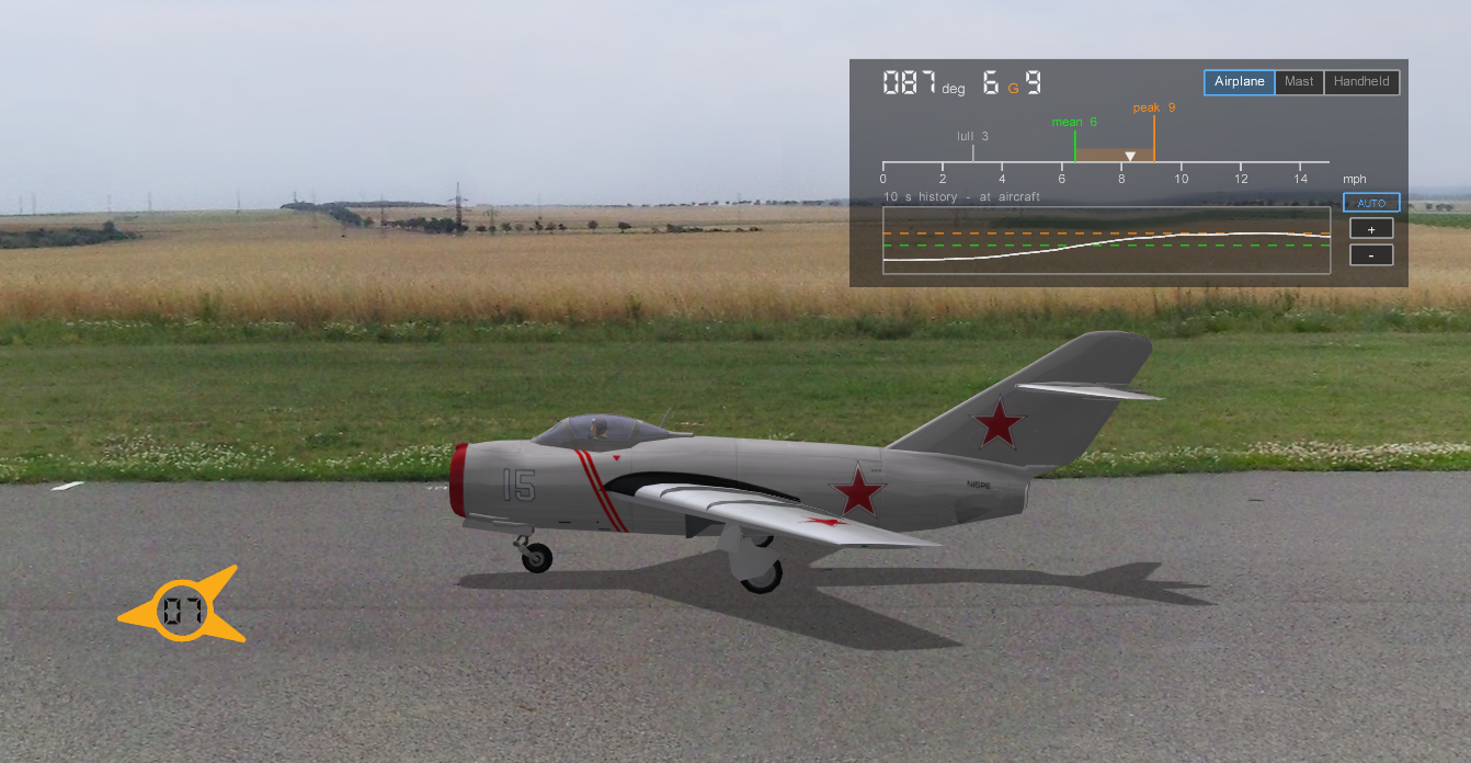
Wind Meter Left Shift + W .
Wind Vectors
Widgets | Wind Vectors draws the wind as a grid of red arrows around the airplane, so you can see the wind field the airplane is flying through. The submenu has Show, sliders for the grid size, spacing, and arrow scale, an arrows-per-frame readout, and Reset to Power Tools Values. Power Tools sets the startup values.
21.10. Attitude Indicator
Press Left Shift + Y for a round artificial horizon with a
pitch ladder and bank scale, plus a green flight path marker showing
where the airplane is actually going. The gap between the marker and
the wings is the angle of attack, the stall warning you cannot see
from the ground. Widgets | Attitude Indicator has
Show and Flight Path Marker, so the marker can be turned off on
its own.
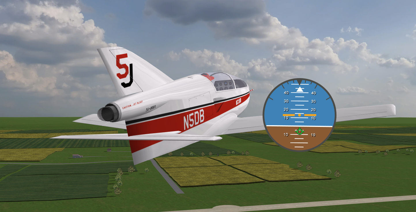
Attitude Indicator Left Shift + Y .
21.11. Wireframe Airplane
Press Left Shift + P for binoculars on a distant airplane. A
small corner square draws your airplane as a white line silhouette at
its live attitude, magnified, as seen from the camera, so its attitude
reads when the airplane itself is a dot.
Three modes are on Widgets | Wireframe Airplane. They are Off, Always, and Auto, which shows it by itself past a set range (default 500 ft). Power Tools sets the mode, the auto range, the size, the start position, the background opacity, and which wireframe file it draws from.
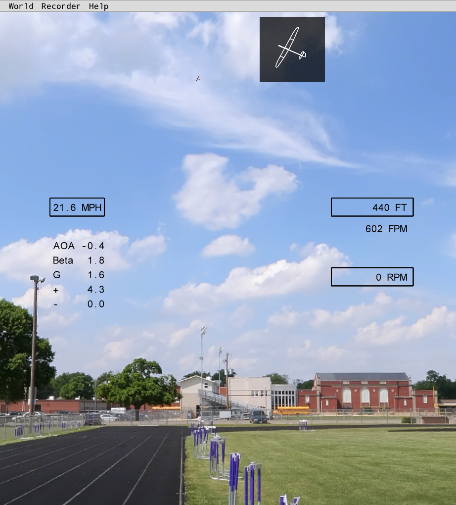
Wireframe Airplane Left Shift + P .
21.12. Variometer
Turn on the Variometer by pressing Left Shift + V .
It will show your rate of climb.
In Options | Sound/Music you can also turn on the
Variometer Sound (faster, higher beeps mean more lift).
The variometer sound represents the change in the total energy, i.e., a
reading that would come from a total energy variometer.

Variometer Left Shift + V .
21.13. Timer (Flight Log / Timers)
The Timer widget is turned on by pressing Left Shift + L . It shows
a readout of the flight time log and up/down timers and their controls. In
the example below, it is showing the “Total Time” of flight for all
models to be 6 hr 51 mins (when the screenshot was taken). This time
will be literally your logbook total flight time since the simulator
was installed on your computer. The “Model Time” is the current
flying time for the particular model being flown (when the screenshot
was taken). It is 55 mins. As flying continues, these timers
automatically keep track of your flight time. Below the first line
are the Count Up / Count Down timers for the Flight Session. The
Count Up timer is turned on by pressing the START/STOP button,
and the timer is reset by pressing the RESET button. The Count
Up time is showing 17 sec. The Count Up time only starts when you
press the START/STOP button. The Count Down timer counts down from a
time you set. The setting is made using the “Min” and “Sec” Up / Down buttons. The
Count Down timer is controlled by its START/STOP and RESET
buttons. The Count Down timer is set here for 4 mins, and it is not
yet turned on (not yet counting down). In the sim, it is
possible to associate voice callouts with the Count Down timer.
To see the flight logs for each airplane, see the Logbook. The Simulation | Flight Time Displays menu also shows the time since reset, since hand launch, this session, and total.

Timer Left Shift + L .
21.14. Landing Target
You can practice your spot landings with the Landing Target widget.
Press L to start. The landing target will be on the ground nearby
your position, and the scoring widget will show on-screen. After
landing and coming to a stop, the distance to the center of the target will
be shown. The blinking yellow indicator means that your position is being
tracked while your aircraft is still moving. The indicator will turn
green once the aircraft has stopped moving and the distance will be
displayed as shown below. Hold T to look at the target
(a Snap View). The target also shows
as a circle on the Field Map.

Landing Target L .
21.15. Radar Gun
The Radar Gun turned on by pressing R can be used to continuously
take a snapshot of your flight speed. When the display is slowly
flashing the speed is accurate. It will flicker when the speed is
changing too rapidly to give an accurate reading. The image below
shows it being used in a pylon race together with the binoculars inset
window and a map showing the course pylons.

Radar Gun R .
21.16. Hover Training Assistant
You can learn to hover airplanes with the Hover Training
Assistant™, turned on by pressing O . The lower bottom switch on
the widget can be used to turn the assistance on and off. Use the
green +/- buttons to increase/decrease the amount of assistance. When
set to the maximum value hovering will become very easy and is a great
place to start learning. Lowering it will make the hovering more
natural until at the lowest value the assistance is effectively turned
off. No matter what the setting, during normal cruise flight, the
assistance setting has virtually no effect, i.e., it cannot be “felt”
in the control sticks.

Hover Training Assistant O .
21.17. Inset Window
To open the Inset Window, press I . The default view is
“Binoculars” which will keep the aircraft zoomed in. The drop down
menu lets you pick many other views such as the one shown below that
always faces north. The Inset Window works for both Pano and 3D
flying sites. The Inset Window works during a regular Flight
Session but not during playback of Recordings or during Flight
Training sessions.
For more details about the Inset Window, see Cameras | Inset Window Widget.

Inset Window I .

Inset Window I showing all 10 views available for 3D flying sites.
21.18. Replay Panel
The Replay Panel (formerly the Flight Recorder Playback Tool) can be
turned on using the Backspace key during a Flight Session. The
panel can be used to restart, reverse, pause, slow-motion, play, and
fast-forward. The flight recordings being played back are ones that
you select from Fly Screens that allow for playing back recordings.
The green bar advances through to the end of the flight.
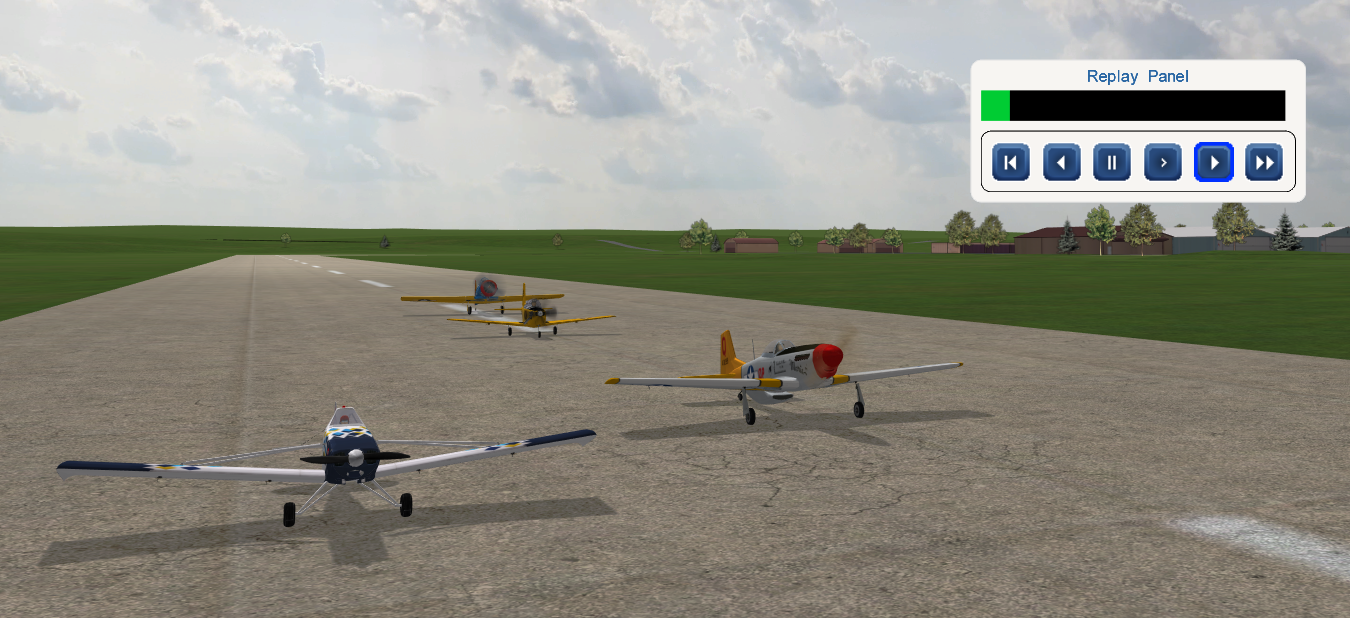
Replay Panel Backspace .
21.19. Sky Grid
Turn on a Sky Grid™ for flight reference by pressing
Left Shift + G -
a favorite feature in SeligSIM (also marketed as FS One) since 2006.
The choice is remembered between flights.

Sky Grid Left Shift + G .
21.20. Tow Force and Towline Tension Plot
Towed launches (winch, hi-start, aerotow) show a pull-force bar automatically. It runs green through the comfortable range and red past the maximum you set, and it gives the pull in pounds and as a multiple of the airplane’s weight. The Towline Tension Plot is a strip chart of the same. Both are on the Widgets menu, and both linger for 30 seconds after the line releases, long enough to read the peak pull after the launch rather than during it. See Takeoff Options and Options | Towlines.
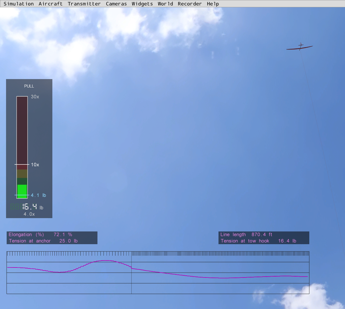
Tow Force bar and Towline Tension Plot during a hi-start launch, about halfway up. The bar reads the pull in pounds and as a multiple of the airplane’s weight. The plot at the bottom is the line tension over time.
21.21. Hand Launch Settings
Press Left Shift + K (or Simulation | Hand Launch Settings on the menu bar) to open the Hand Launch
Settings window, a pop-out that holds the Power Tools throw settings
so you can tune the launch without leaving the flight. It works for
hand launch, hi-start, and winch flights.
The sliders are in groups, top to bottom. Arm Cocking sets how long and how far the arm draws back. Throw sets the throw duration and its peak g-force. Launch Height Relative to the Pilot raises or lowers the release point. Attitude at Release sets the bank angle at release and a random variation on it. Launch Direction shows the current aim (azimuth and elevation, which normally follow the mouse) and lets you fix the direction instead. Elevator Preset on Timer holds an elevator deflection for a set time after release. Extras toggles the point-of-release marker, the toss sound, and the hand launch force display.
Drag a slider, nudge it with the arrows, or Ctrl + click it to
type a value. The next launch uses the new values. They last for the
run, and Power Tools is never changed. Power Tools values and
Standard restore either set. Save Settings keeps one saved set on
disk, and Reload Saved Settings brings it back, so a launch you like
survives the run. Esc closes the window.
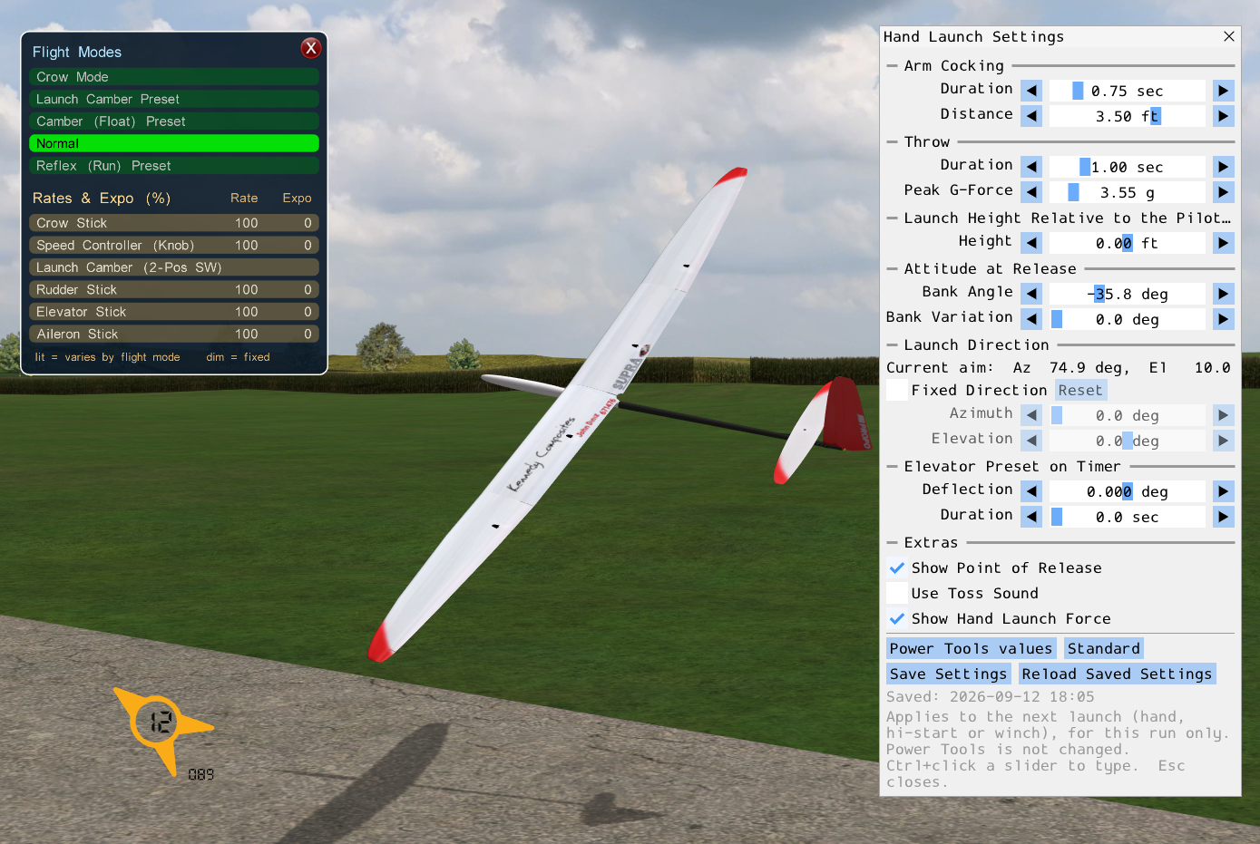
Hand Launch Settings Left Shift + K . The Supra
sailplane is set up for a left-bank hand launch (bank angle
-35.8 deg). Also open are the Flight Modes & Rates/Expos
panel at left and the Wind Compass with its direction readout at
lower left.
21.22. Save Position to File
To save the current position of the aircraft to a
local file press ' . The position gadget will be displayed and
show the point in the North-East-Down coordinate system. Pressing
' repeatedly will save a point for each key press. The points are
saved to the position_data.txt file in the SeligSIM
installation folder. The tool (shown below) can be used to show the
position continuously if the “CLEAR” button is clicked once. Click “X” to close the widget.
The widget shows the current position, the last position, and the
distance between the two, which makes measuring distances in the sim
easy.
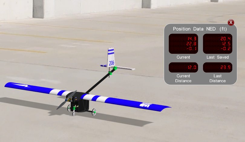
Save Position to File '
(file: position_data.txt ) .
21.23. Transmitter Display
To see your stick inputs on-screen, press E to show the
Transmitter Display. It is on the Transmitter menu. Press E
again to cycle through the transmitter textures (InertiaSoft, TacCon,
gimbals only, transparent, and more). The texture name shows on
screen.

Transmitter Display E . The red dots are the stick
positions, here with the throttle at idle.
21.24. Transmitter Panels
The Transmitter menu holds a set of panels that show the radio at
work, from what each stick and switch does, to what the servos are
doing, to how the mixes are wired. Each opens with Left Shift plus a
letter. Open Tx Basics and Open Tx Full on that menu lay out
whole sets of them with one click, and Close All clears them. The same
panels are available in the
Edit Transmitter window, where they
stay live while you edit.
Flight Manual ( Left Shift + I )
The airplane’s controls table, built live from your controller. It lists every stick, switch, knob, and key and what each one does. It is the Flight Manual for the airplane you are flying, as seen through the controller you are holding. Below the controls, the Mixes list shows each mix and what turns it on, a key or Always On.
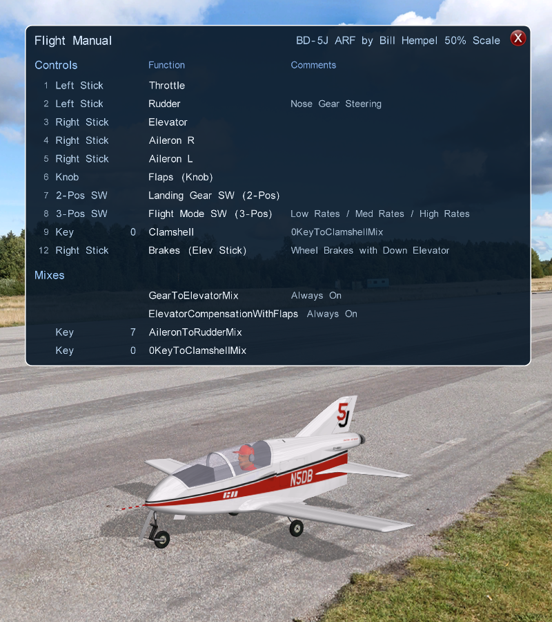
Flight Manual panel Left Shift + I , for the BD-5J. Each
row is one control on your transmitter, with its function and a
comment. The clamshell is on key 0 here, and the wheel brakes
are on down elevator.
Flight Modes & Rates/Expos ( Left Shift + E ) and Flight Modes & Mixes ( Left Shift + F )
Both panels show the flight modes at the top, with the active one lit, and change live as you flip the switch. Rates/Expos lists each channel’s active rate and expo (a control with no rate or expo reads 100 / 0, and a switch channel prints no values, since rate and expo mean nothing on a 2- or 3-position switch). Bright rows are the ones the flight-mode switch changes, and dim rows are fixed. Mixes lists each mix, lit when it is on, with what turns it on at the right, a key number or Always On.
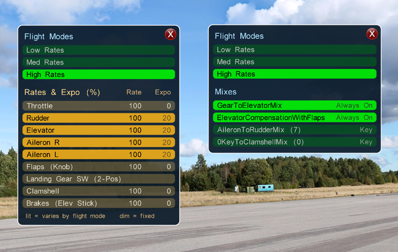
Flight Modes & Rates/Expos Left Shift + E (left) and
Flight Modes & Mixes Left Shift + F (right), both in
High Rates. The amber rows are the controls whose rates and
expo change with the flight mode. Two mixes are on and always
on, and two wait on a key.
Flight Modes & Channels ( Left Shift + C )
Every channel, what drives it (an axis or a key) and what it drives (the servos), with the active flight mode lit.
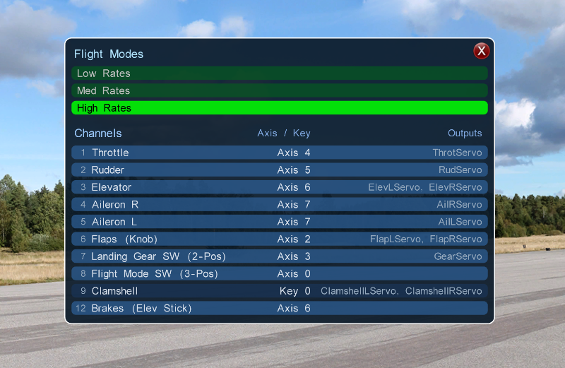
Flight Modes & Channels Left Shift + C . Elevator on
axis 6 drives two elevator servos, and the clamshell on key 0
drives two clamshell servos.
Flight Modes & Offsets ( Left Shift + T )
Each channel’s offset in every flight mode, one column per mode with the active mode lit. expr means the value is inherited from the channel’s expression rather than set for that mode. The values are in channel travel.
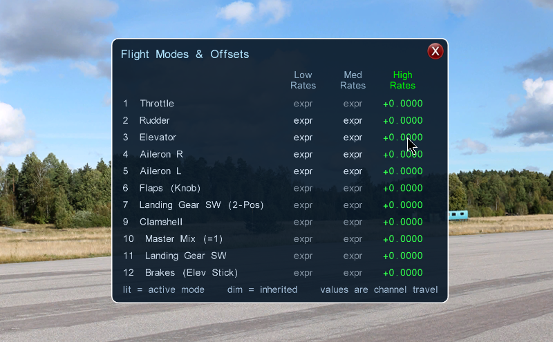
Flight Modes & Offsets Left Shift + T . The High Rates
column is active and all offsets are zero.
Servos ( Left Shift + S ), Deflections ( Left Shift + D ), and Axes ( Left Shift + A )
These three show the signal at three points. Axes is the raw controller, each axis as a slider with the raw count beside it (the Axes Raw Counts item on the menu turns the counts on and off) and the functions it drives at the right. Servos is one travel bar per servo, scaled to its real configured limits, so a bar on the stop explains why the airplane will not roll any harder. A red tick on a bar is the command the servo is following, and it hides once the servo has caught up. Deflections is the result, each control surface in degrees.
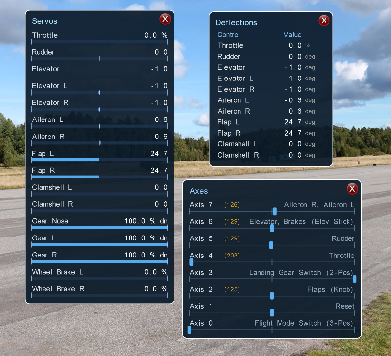
Servos Left Shift + S , Deflections Left Shift +
D , and Axes Left Shift + A , open together. The
flaps are at 24.7 deg on both panels, and the flap knob is
axis 2 with its raw count in amber. No red ticks show because
every servo has caught up.
Mix Map ( Left Shift + Z )
How the whole radio is wired, as a grid. Rows are the master channels and columns are the slave channels. A lit cell is a mix that is on, a dim cell is one that is off, a small square is a mix onto the channel’s own surface, and a number is how many mixes share the cell. The bar at the top names the selected mix, and the arrows step through them. The grid re-wires when you switch flight modes. Click a cell and the Mix Bench opens on that mix.
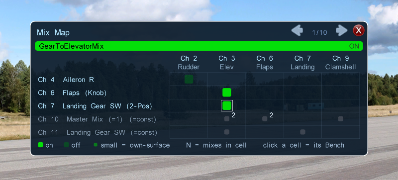
Mix Map Left Shift + Z , on GearToElevatorMix, the
first of ten mixes. The landing gear switch feeds the elevator,
and the flap knob feeds it too through a second mix.
Mix Bench ( Left Shift + X )
See what one mix actually does. The Mix Bench shows the selected
mix in full, its type and table, the master channel with a live
slider, its transfer curve with a live dot riding it, and the
contributions to the slave channel added up line by line, through
the gain, the mode offset, and the clamp, down to the slave channel’s
output. Left Shift + , and . step to the previous and
next mix, and the Mix Map follows. Crow and the other
multi-channel mixes get full parameter cards with a mini plot per
surface.
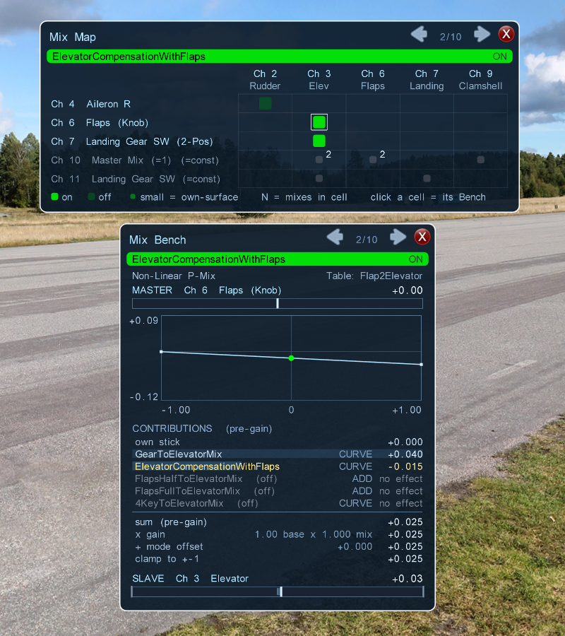
Mix Map and Mix Bench Left Shift + X on the same mix,
ElevatorCompensationWithFlaps, the second of ten. The flap knob
is the master, the curve trims the elevator a little as the flaps
come down, and the contributions list shows this mix and the gear
mix summing into the elevator.
21.25. Data Monitor, Messages, and Frame Rate
The Simulation menu has Show Messages, Show Data Monitor, and
Frame Rate ( F ). The Data Monitor and the right-edge readouts
(timers, frame rate, line tension) are one aligned panel, with labels
on the left edge and values and units on the right, so decimal points
hold still. Its first row reports the real physics rate, and the
Frame Rate row above it pairs with it. What the Data Monitor
shows is chosen in Power Tools, or in flight with Simulation | Data Monitor Settings…, a window that picks which of the
80 readouts show, with the monitor’s switch and its text size.
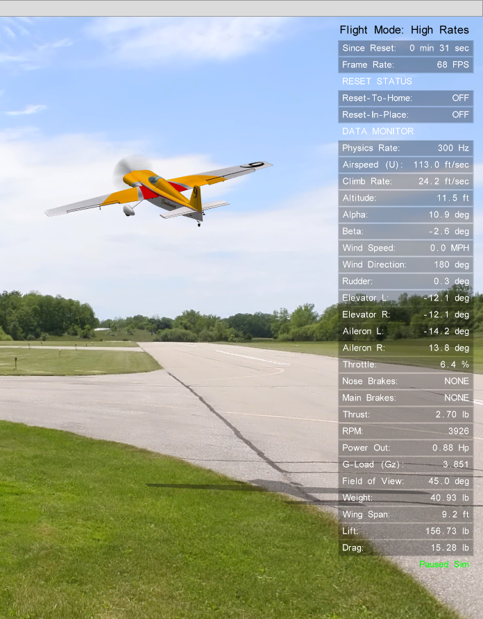
Data Monitor panel, with the Since Reset, Frame Rate, and RESET STATUS rows above it in the same aligned column. Its first row is the physics rate, 300 Hz here. The Sundowner is climbing out just after takeoff, with the sim paused.
The rows adapt to the airplane. An airplane with flaps, clamshell doors, or wheel brakes gets rows for them. The brake rows show whether brakes are available and whether they are on.
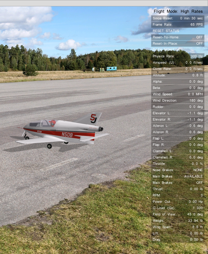
Data Monitor for the BD-5J on the runway. Rows for the flaps, the clamshell doors, and the main wheel brakes appear because this airplane has them.